The first document is three pages stapled together. The originals were faded with age. They were photocopied and the photocopy gone over with a sharp 2B pencil. The retouched copies were then scanned and these are shown here.
The document was a Schedule of Machines to Agreement for Sale between International Business Machines and the University of Newcastle upon Tyne.
The original document was just a list of 4-digit components with UK Selling Price
and the 20% Discounted price. Someone (Me) has handwritten what the components were,
by looking them up in the IBM System/360 Installation Manual - Physical Planning,
a page of which is the next document.
Clicking on a picture will bring up a larger picture, use the ⇦ to return to the text.
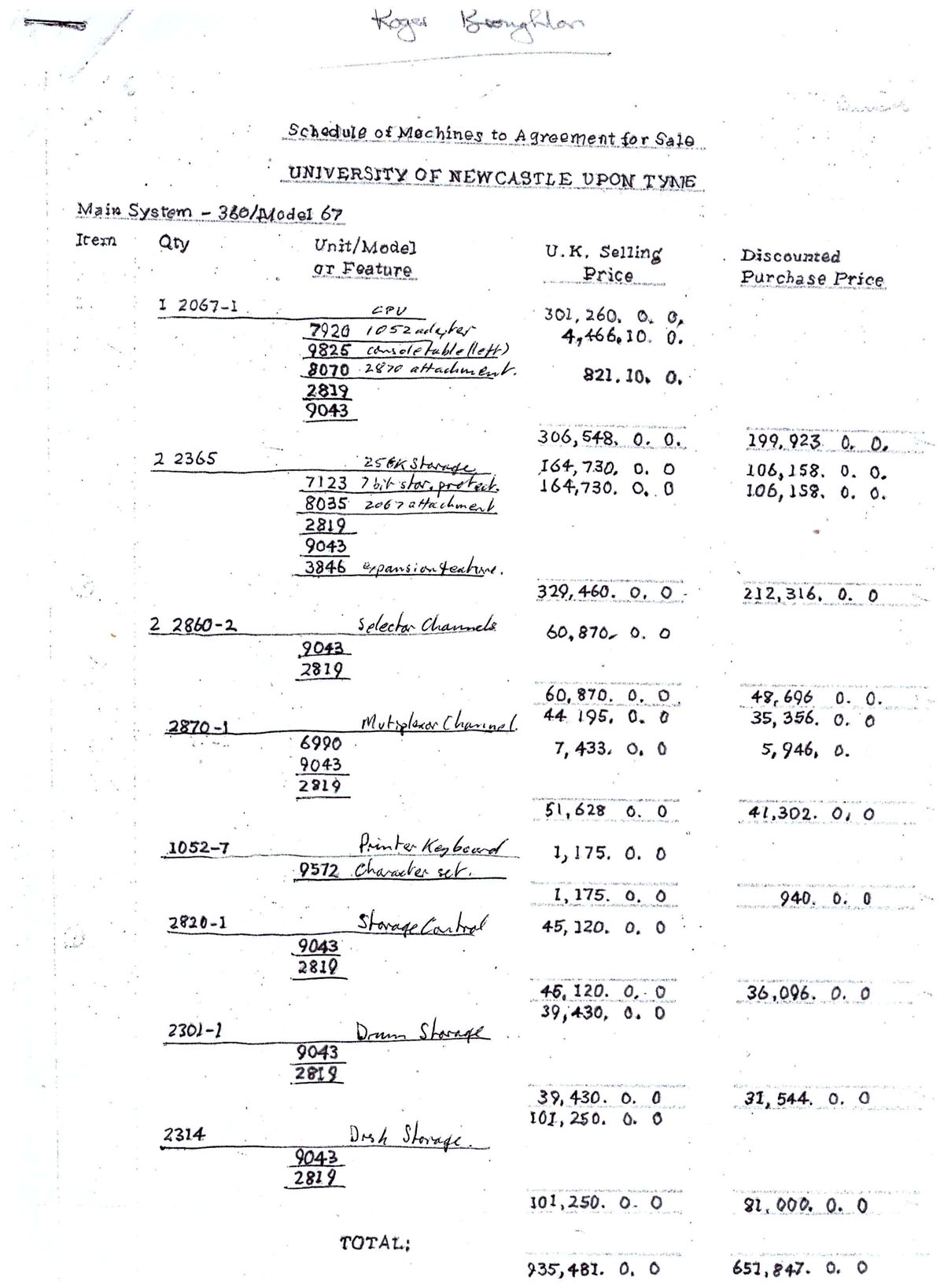
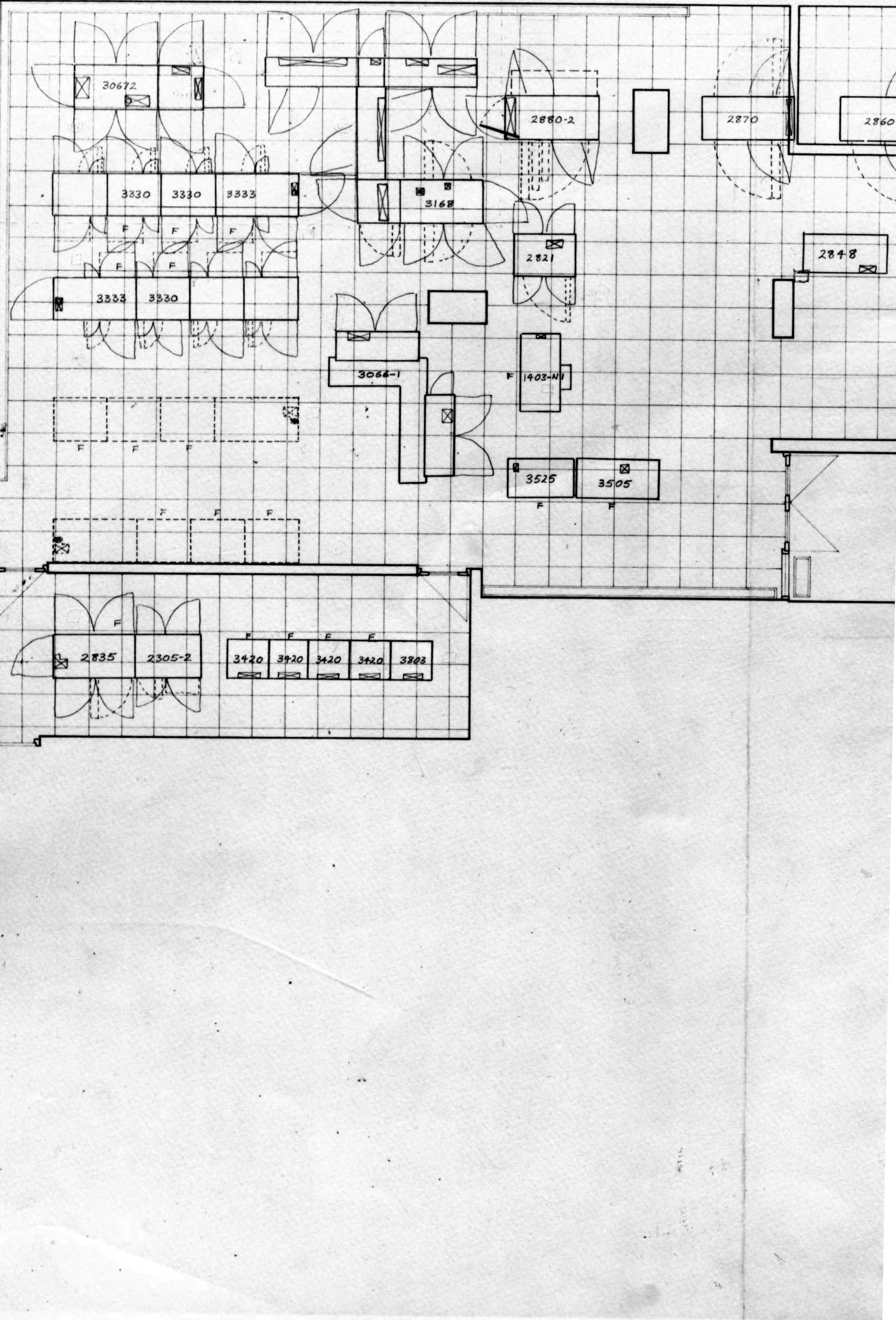
The first page is about the CPU, RAM, console, Channels, drum and disk storage.

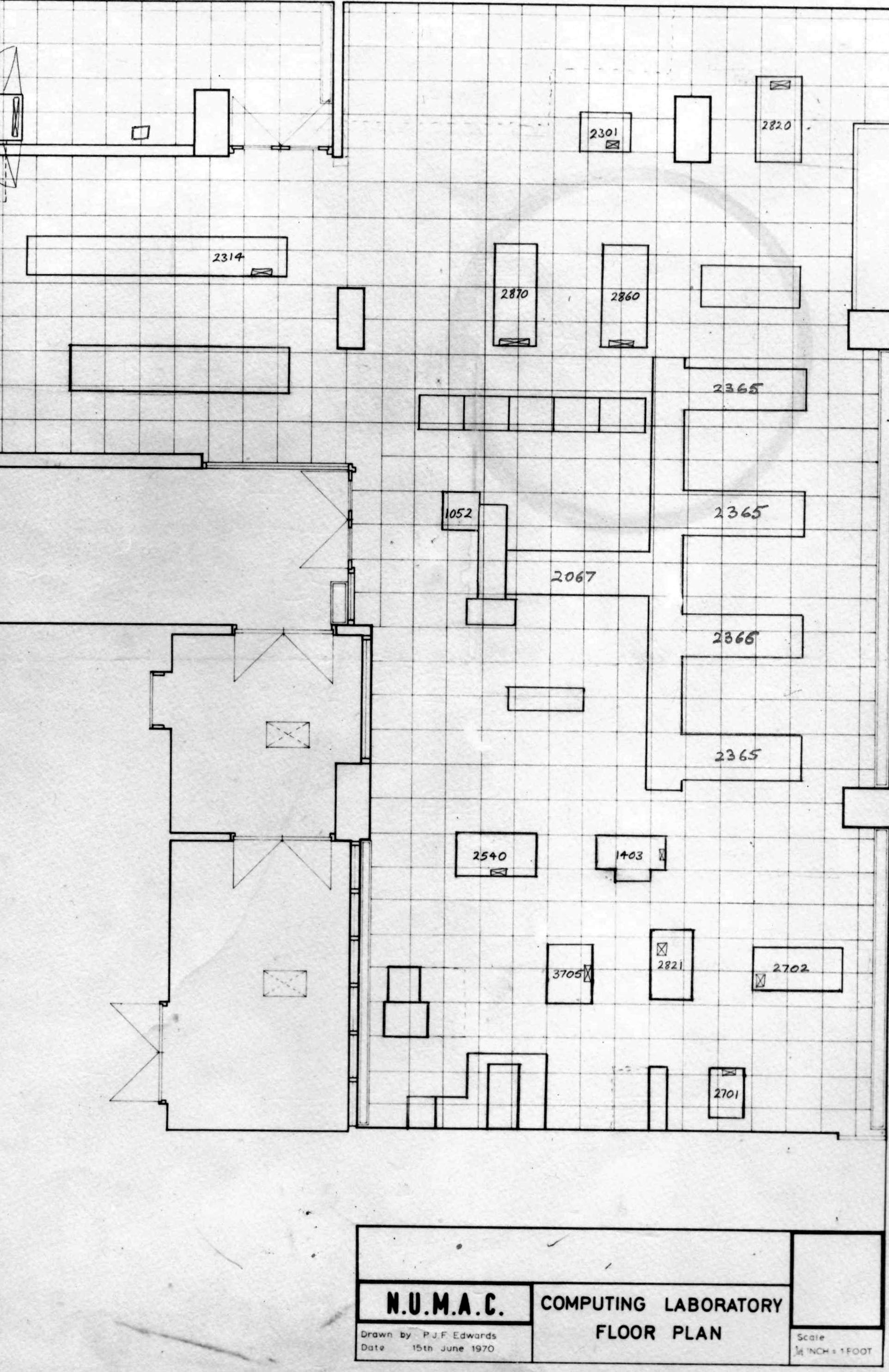
The second page shows communication peripherals and paper tape reader.
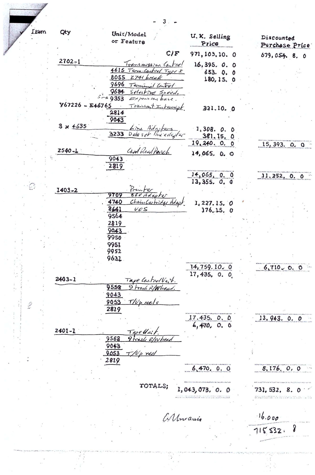
The final page: card reader/punch, line printer and magnetic tape drives.
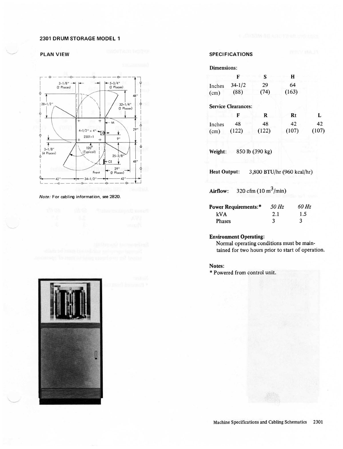
This is a page from the Physical Planning manual. The 4-digit number 2301 is a DRUM STORAGE MODEL 1. The diagram gives the dimensions of the cabinet, the clearances required for the doors and gates to open and where the hole in the floor has to be cut.
Other information is the weight, heat output and power requirements.
A list of all the System 360/67 components giving weight, Kwatts and cost is at www.staff.ncl.ac.uk/roger.broughton/firmware/360components.htm
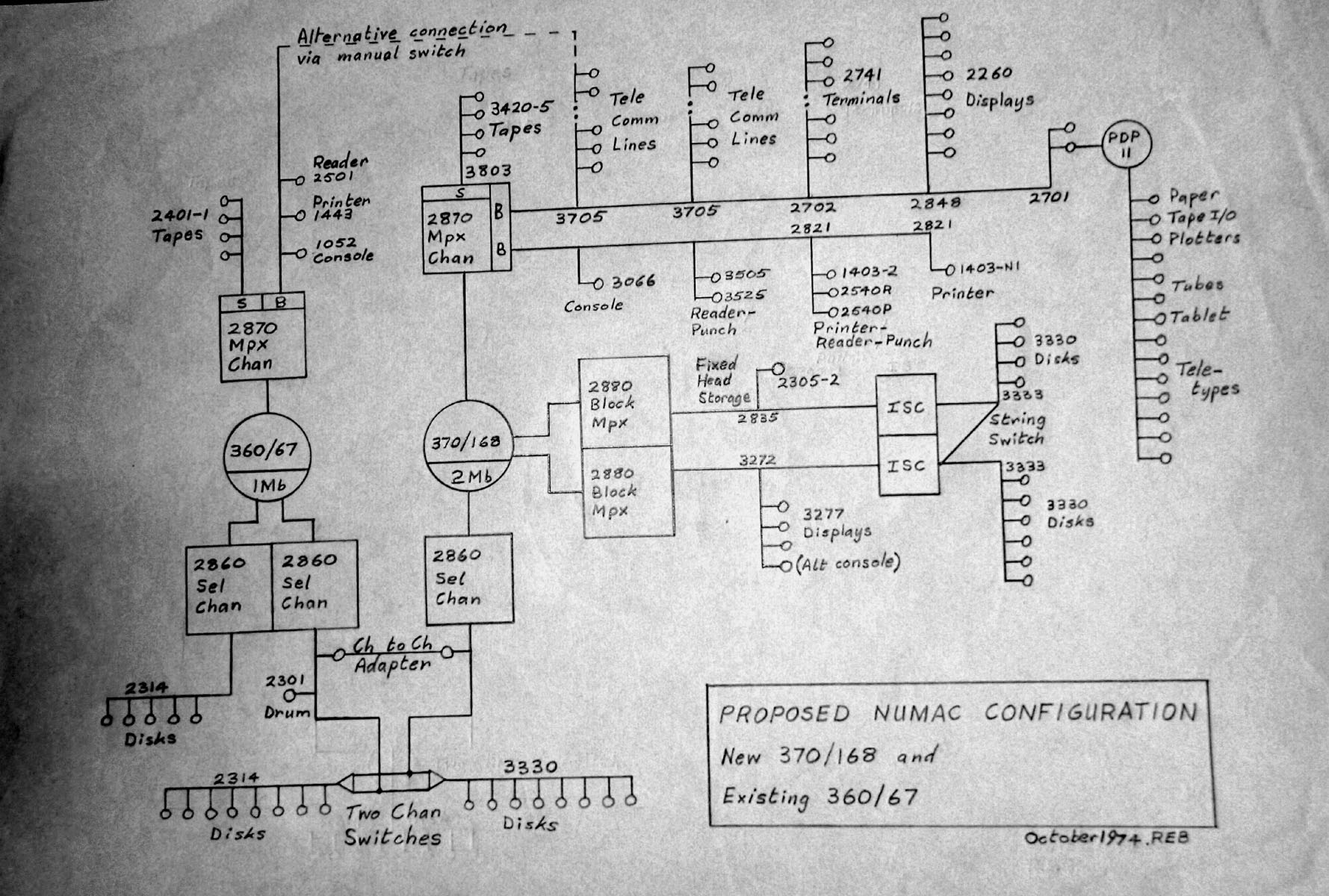
This diagram shows how the components were connected. On the left is the System 360 Model 67 which the first three-page document refers to. On the right is the next computer, the System 370 Model 168. The two computers were connected by sharing two banks of disks.
Just looking at the 360/67 on the left, central is the CPU and 1Mb of RAM (Random Access Memory). Connected to the RAM were Channels. Above the CPU was a 2870 Mpx Channel, this could support slower devices. Below were two 2860 Selector Channels that connected fast devices whose data transfer could not be interrupted.
Each device, marked as a little round circle, was connected via a Control Unit to the Channel. All Control Units looked the same to the Channel. The device side of the Control Unit was tailored to the devices attached.
When an I/O operation was initiated by the CPU, a "Start I/O" command was issued to a Channel giving the address in RAM of a program of CCWs (Channel Command Words). The CPU would then continue executing instructions whilst the channel executed CCWs. Whenever a Channel and the CPU wanted access to RAM, the Channel always won. Input/Output was always the limiting factor in the execution time of programs.

The previous diagram showed how the two IBM computers were physically connected, this diagram shows how they were software connected.
During the daytime the 370 ran MTS (Mitchegan Terminal System) which provided an interactive service to users sitting at terminals issuing MTS commands or running programs and seeing the result so they could interact to go forward or correct.
For the whole day the 360 ran MVT (Multiprogramming Variable number of Tasks) processing batch jobs.
In the evening the interactive MTS service was closed and the MVS (Multiple Virtual Storage) batch processing service was started on the 370. This is when this diagram shows how the two computers processed the batch jobs.
The System 360/67 on the left ran the MVT . The Input/Output was controlled by a program called HASP(1).
The 370/168 on the right ran the MVS operating system. The Input/Output was done by JES2 (Job Entry Sub system).
Both HASP and JES2 had their own SPOOLing(2) disks which were accesible to both and by use of internal reader program and transfer progran input and output could be moved between the two.
(1) HASP (Houston Automatic Spooling Priority) system. It was an addition to the IBM Operating System and greatly enhanced it. It controlled all the job input and output devices including those remotely connected via telecommunication lines. It allowed computer operators to control the jobs in the input/execution/output queues. It was a large program, 78KByte, written in Assembler code. A listing of the HASP program can be seen at www.staff.ncl.ac.uk/roger.broughton/museum/iomedia/cl.htm
(2) The first computers were used by the people who wrote the programs. They took it in turns to take control, reading in their program, starting it, that read in the input data, and as it executed printed the output. Each card read and line printed took about a 1/10 second which meant the CPU was at least 20% idle and if there was little computation it would be over 90% idle.
In the 1950s magnetic tape drives became available and a way of working using SPOOLing (Symultanious Peripheral Operations OffLine) was devised. An input device was connected to a Tape drive and the input written to the magnetic tape. The tape was moved to the execution input drive. The execution was begun with output going to the output tape. Both the input and the output was tape drive speed at least ten times faster than raw input/output. Whilst the execution phase was going the previous output tape was being printed and the next input tape being created.
Then in the 1960's disk drives became available. The spooling device no longer was a sequential device like the magnetic tape, it was a direct access disk. Now several input devices could be read and data written to the SPOOL disk, several executions read from and output to disk, output printed to several printers/card punches.
It also meant that execution and print processes could be prioritised, hence the P in the HASP acronym.
(As Operations Supervisor of the computer room I could enter a top priority job that would go to the head of the execution queue, then head of the print queue, such that when I removed the card deck from the reader I could see my output on the printer.)