To the top right is a panel. We have it in the museum:
(I did not save it, I would like to know who did.)
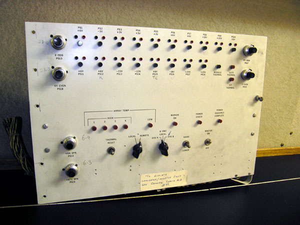
Here it is.
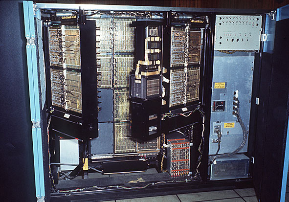
There were 18 power supplies in the 2365 Core Storage Unit.
This panel incorporated controls to sequence the powering on of the power supplies.
If all had been powered on at once
the inrush of current would have blown fuses/tripped circuit breakers.
In addition there were six potentiometers for adjusting the voltages of the core stores.
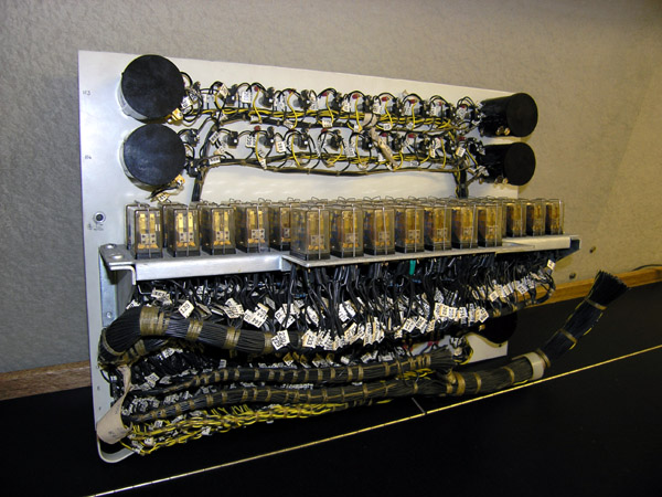
On the rear of the panel there were micro switches that powered on each power supply
awaiting a powered-up signal from one before sequencing the power up of the next.
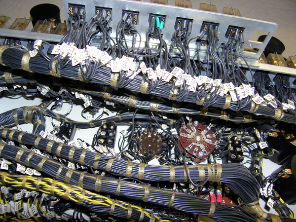
All this is hand assembled, soldered, labelled.
Two of the potentiometers are the black cylinders top left and right, two more are bottom right.
The potentiometers are mentioned because they were used to "shmoo" the storage box
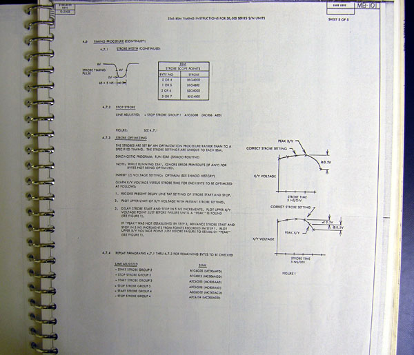
This is the page from the engineer's manual that has the timing instructions for
the 2365 BSM storage units.
The page says:
STROBE OPTIMIZING

THE STROBES ARE SET BY AN OPTIMIZATION PROCEDURE RATHER THAN TO A
SPECIFIED TIMING. THE STROBE SETTINGS ARE UNIQUE TO EACH BSM.

DIAGNOSTIC PROGRAM, RUN E3A1 (SHMOO ROUTINE)

NOTE: WHILE RUNNING E3A1, IGNORE ERROR PRINTOUTS (IF ANY) FOR
      BYTES NOT BEING OPTIMIZED.

INHIBIT (Z) VOLTAGE SETTING; OPTIMUM (SEE SHMOO HISTORY)

GRAPH X/Y VOLTAGE VERSUS STROBE TIME FOR EACH BYTE TO BE OPTIMIZED
AS FOLLOWS:

1. RECORD PRESENT DELAY LINE TAP SETTING OF STROBE START AND STOP.

2. PLOT UPPER LIMIT OF X/Y VOLTAGE WITH PRESENT STROBE SETTING.

3. DELAY STROBE START AND STOP IN 5 NS INCREMENTS. PLOT UPPER X/Y
   VOLTAGE POINT JUST BEFORE FAILURE UNTIL A "PEAK" IS FOUND
   (SEE FIGURE 1).

   IF PEAK WAS NOT ESTABLISHED BY STEP 3, ADVANCE STROBE START AND
   STOP IN 5 NS INCREMENTS FROM POINTS RECORDED IN STEP 1, PLOT
   UPPER X/Y VOLTAGE POINT JUST BEFORE FAILURE TO ESTABLISH A "PEAK"
   (SEE FIGURE 1).
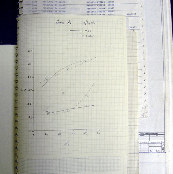
This a plot of "Box A" both odd and even bytes.
Why is the process called to SHMOO the core storage box?
A shmoo is a cartoon creature, created by Al Capp, in 1934.
The shmoo is shaped like a plump bowling pin with legs, but no arms.
Shmoo became the name for the graphical display, the Shmoo plot,
most likely because the region where a particular device passes or fails,
plotted against the sweep variables,
may have some of the rounded curves and shifting nature of the cartoon figure.
To shmoo is to run a test repeatedly while varying one or more parameters